Status: internal measurement, not peer reviewed. See §7 for what would be required before this is publishable, and §6 for why it should not yet be relied on as an engineering result.
1. Summary
We measured how the peak injection pressure predicted by a full-3-D finite-volume mold-filling solver depends on the number of cells resolving the part's wall thickness. On a 2 mm slit in VICTREX 450G PEEK at a prescribed volumetric flow rate, the predicted peak pressure was 51.9 MPa at 3 cells across the gap and 209.2 MPa at 6 — a factor of 4.0, still rising, with no sign of convergence at the finest resolution we could afford.
We report this because the curve appears not to exist in the published literature. Vendors publish minimum element counts (Autodesk Moldflow: minimum 6, default 10; Moldex3D: 7–11) as guidance, but we found no published pressure-versus-resolution curve from any vendor or peer-reviewed source, and no derivation of those minima from the underlying physics.
Two qualifications belong in the summary, not buried below.
The 4.0× is not purely discretization error. §4 establishes that freeze-off in this solver is quantized to the grid, and that the thermal boundary layer (δ ~ √(αt) ≈ 0.17 mm) is a fraction of a cell at every resolution tested. So the 3-cell case very likely does not resolve the frozen layer at all, while the 6-cell case begins to. Part of the 51.9 → 209.2 MPa change is therefore a physical mechanism switching on as the mesh starts to see it, not a discretization error converging. This does not weaken the "not converged" conclusion — arguably it strengthens it, since a mechanism that appears only above some resolution cannot have converged below it — but the two effects are confounded in these data and we cannot separate them.
Our measured range sits at or below every vendor minimum we cite. Moldflow asks for at least 6 and defaults to 10; Moldex3D asks 7–11. We measured 3 → 6. "Not converged across 3–6 cells" is close to what that guidance already implies, so the novelty here is the magnitude and the existence of a curve, not the fact of non-convergence. The closest-matched guidance is MAGMASOFT's — the only Cartesian code among them — which sets a floor of three cells across thin walls, a threshold our range straddles rather than clears.
We also report a methodological failure mode that invalidated our own first attempt and would invalidate anyone else's: an injection-pressure cap silently censors the very quantity being converged.
2. The gap
Three independent literature searches (§8) returned the following clear negatives:
- No pressure-vs-elements-through-thickness curve is published by any vendor or in the peer-reviewed literature. The 2023 review of filling-phase modelling (Polymers 15(21):4220) classifies methods and rheology models but gives only qualitative mesh labels ("coarse / medium / fine / ultrafine").
- No published derivation of a required through-thickness element count from frozen-layer physics. Every number in circulation is vendor guidance or a methods-section choice.
- Time-step independence is essentially never reported for filling, though mesh independence routinely is.
Vendor guidance that does exist, for calibration:
| source | requirement |
|---|---|
| Autodesk Moldflow, 3-D | minimum 6 elements through thickness; default 10 |
| Moldex3D boundary-layer mesh | minimum 7, up to 11 |
| MAGMASOFT (a Cartesian code) | "at least three elements side by side in the thin wall areas… If there are less than three elements, the impact of wall friction is too strong" |
The MAGMASOFT figure is the closest analogue to our discretization, being the only Cartesian code among them.
3. Method
Solver. Uniform Cartesian voxel grid; MAC staggered arrangement (pressure at cell centres, velocity components at faces); creeping (inertia-free) flow of a generalized-Newtonian melt; Cross-WLF viscosity with a two-domain Tait pvT description; no-slip imposed by zeroing every velocity face touching a non-fluid cell (stair-step immersed boundary); pressure fixed at zero on flow-front cells; Uzawa iteration on the pressure Schur complement with inner conjugate-gradient momentum solves; melt front advanced by donor-cell upwind advection of a fill fraction.
Geometry. A 20 × 4 × 2 mm rectangular slit, edge-gated across the whole
x = 0 face. This is an idealization of a "tag die", chosen because slit pressure
drop is the cleanest possible probe of gapwise resolution: it scales as
h_gap^-(2n+1), so any error in the resolved gap is strongly amplified.
Material. VICTREX 450G PEEK, Cross-WLF (n = 0.4425, τ* = 1.59853e5 Pa, D1 = 3.80118e11 Pa·s, D2 = 403.15 K, A1 = 22.889, Ã2 = 51.6 K), from the manufacturer-supplied simulation data sheet.
Conditions. Melt 375.5 °C, mold 176.9 °C. Volumetric flow rate prescribed to fill the cavity in ~0.3 s at every refinement, so the comparison is at matched fill time rather than matched injection pressure.
Refinement. On cells across the 2 mm gap — the only direction that matters
for this quantity — from 3 to 6, with the in-plane spacing tied to the same h.
Critical protocol point. The injection-pressure cap must be lifted. See §5.
4. Results
| cells across gap | h (mm) | cells | peak pressure (MPa) | coverage |
|---|---|---|---|---|
| 3 | 0.667 | 540 | 51.9 | 1.000 |
| 4 | 0.500 | 1,280 | ≥ 52.8 | 0.490 (froze off short) |
| 5 | 0.400 | 2,500 | ≥ 115.6 | 0.433 (froze off short) |
| 6 | 0.333 | 4,320 | 209.2 | 1.000 |
Not converged. The two comparable full-fill points differ by a factor of 4.0 and the trend is still rising. The 4- and 5-cell rows are lower bounds: a short shot stops before peak pressure is reached, so their values censor downward.
The non-monotone stalling is itself a resolution artifact. Freeze-off is quantized to the grid: the first cell centre crosses the no-flow temperature at some refinements and not others, so whether the slit freezes off short is decided by where the mesh happens to sample the thermal boundary layer, not by the physics. At these resolutions the thermal boundary layer (δ ~ √(αt) ≈ 0.17 mm for a 0.3 s fill at α ≈ 1e-7 m²/s) is a fraction of one cell.
Which means the headline ratio confounds two mechanisms. If the frozen layer is sub-cell at 3 cells and beginning to be resolved at 6, then the pressure rise is partly discretization error shrinking and partly the frozen-layer resistance mechanism itself appearing. These data cannot separate them, and any reading of the 4.0× as a convergence rate would be wrong. Separating them requires either a run with the thermal coupling disabled (isolating the profile-quadrature error) or resolutions fine enough to place several cells inside the skin — which, at δ ≈ 0.17 mm, means cells of ~0.05 mm and roughly 40 across the gap, an order of magnitude beyond what we could afford.
Consequence for engineering use. Under ASME V&V 20, verification precedes
validation: with u_num unbounded, a comparison against measured pressure
traces is not interpretable at any resolution reachable here. The error is also
decision-flipping — the same part quotes under a 75 MPa press at 3 cells and
does not at 6.
5. A methodological warning: pressure caps censor the study
Our first execution of this study was void, and the failure is subtle enough to be worth stating for anyone repeating it.
The solver models a machine injection-pressure limit: when the predicted peak exceeds it, the volumetric source is scaled so the peak sits exactly at the limit. With that cap active at 75 MPa, every refinement above 3 cells saturated:
| cells across gap | reported peak (MPa) | Δ vs previous |
|---|---|---|
| 6 | 75.0000 | — |
| 7 | 75.0000 | 0.00 % |
| 8 | 75.0000 | 0.00 % |
Read naively, those near-zero deltas look like textbook convergence. They are the machine limit being reported back. A pressure cap censors precisely the quantity being converged, and converts a divergent series into an apparently converged one. Any grid-convergence study of injection pressure must run at prescribed flow rate with the cap lifted, and must report coverage so that censored (short-shot) points are visible as lower bounds rather than data.
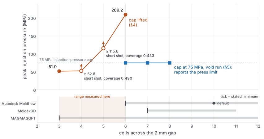
The same slit, with and without the cap. Lifted, the peak pressure quadruples between 3 and 6 cells and is still rising; open markers are short shots, lower bounds only. Capped at 75 MPa, the 6–8 cell runs report the press limit and look converged. The strip below places the measured range against the vendor minima of §2. Plotted from the tables in §2, §4 and §5; the ladder wrote no data file.
We flag this because the failure is silent: no diagnostic fires, and the resulting table is more convincing than the correct one.
6. Threats to validity
Stated in full, because this note reports a solver's behaviour, not the physical world's.
- The solver is not validated. It has documented defects that plausibly affect this curve: a stair-step immersed boundary (wall shear on Cartesian cut-cell grids is reported to converge 2–4× later than pressure), and face-viscosity constructed by averaging cell viscosities rather than from a face shear rate.
- The geometry is idealized. A rectangular slit, not the real die; the CAD for the physical experiment does not exist.
- One material, one condition set. No sweep over
n, melt temperature, or flow rate. Analytic work (not reported here) suggests the profile-quadrature error is only weakly dependent onn, but the frozen-layer sensitivity is not. - Wall clock forced the ceiling. 6 cells across the gap was the practical limit; the curve is unbounded above, so "still rising" is a statement about the range measured.
- Prior art risk. Several key sources were paywalled and read only via abstract (Hieber & Shen 1980; Kim & Turng 2004; CMAME 399:115264). Search budgets were exhausted. Absence in our search is not proof of absence in the field, particularly for a curve that might sit in a thesis appendix or a vendor's internal validation report.
- Single implementation. Everything here is one solver's behaviour. The magnitude of the effect is not transferable; only the shape of the question is.
- Two mechanisms are confounded (§1, §4): discretization error converging and frozen-layer resistance switching on as the mesh begins to resolve the skin. The reported 4.0× is the combination and must not be read as a convergence rate.
- The measured range is at or below the cited vendor minima. Non-convergence across 3–6 cells is broadly what Moldflow's minimum of 6 and Moldex3D's 7–11 would lead one to expect. The contribution is the curve and its magnitude, not the discovery that coarse meshes are inadequate.
7. What would make this publishable
- A mesh-convergence study on a geometry with an analytic or high-fidelity reference (e.g. a 1-D gapwise solution, or a converged body-fitted 3-D result) so the curve can be anchored rather than merely observed to move.
- Independent reproduction in a second solver, ideally one with a body-fitted mesh, to separate discretization error from immersed-boundary error.
- A material sweep (at minimum a shear-thinning index range) and a fill-time sweep, since the frozen-layer fraction is the suspected driver and it depends on both.
- Grid-convergence-index (Richardson) analysis with the observed order of convergence reported, rather than a raw ratio.
- A completed prior-art search including paywalled sources and vendor validation reports.
8. Sources
Vendor guidance and reviews consulted for §2:
- Autodesk Moldflow Insight help, "Meshing a model in 3D" and "Factors affecting analysis accuracy" (minimum 6 / default 10 elements through thickness).
- Autodesk University handout SM5706-P (minimum 6 for flow analysis, ideal 8+).
- Moldex3D boundary-layer mesh documentation (minimum 7, up to 11).
- MAGMASOFT 4.4 manual, mesh-generation chapter (at least three elements across thin walls).
- Baum, Anders & Reinicke, "Approaches for Numerical Modeling and Simulation of the Filling Phase in Injection Molding: A Review", Polymers 15(21):4220 (2023) — qualitative mesh labels only.
- ASME V&V 20 (verification precedes validation;
u_nummust be bounded before a comparison error is interpretable).
Raw data and the generating script are recorded internally, in the FutureMold engineering repository. They are not published with this note; every number the argument rests on is in the tables above.
Colophon — authorship and AI assistance
Author (responsible natural person): Anderson Brunsvold, FutureMold.
AI assistance disclosure. This note was produced with substantial AI assistance, and the extent is material to how it should be read:
- Literature search and synthesis: AI-conducted. The surveys behind the "no published source" claims were run by AI agents. Their search budgets were exhausted and several primary sources were paywalled and read only via abstract or secondary description. The novelty claims rest on those searches and inherit their limits — see the threats-to-validity section.
- Measurements: AI-executed, human-directed. The experiments were designed, scripted and run by an AI agent (Claude) working in the FutureMold repository, under direction from the author. The raw outputs are in the session record and the repository's reference documentation.
- Drafting: AI-written, human-reviewed. The prose is AI-drafted. It was reviewed by the author, and that review caught substantive errors — including, in this series, a claim that contradicted its own data table and a headline figure that conflated two mechanisms. Corrections are marked in place rather than silently applied.
- Not independently reproduced. No result here has been reproduced by a second implementation or a second party.
Standing caveat. Absence of a result in an AI-conducted literature search is weak evidence of absence in the field. Any novelty claim in this note should be re-checked against paywalled and non-indexed sources before it is relied upon.